UDN
Search public documentation:
MaterialsCompendium
日本語訳
中国翻译
한국어
Interested in the Unreal Engine?
Visit the Unreal Technology site.
Looking for jobs and company info?
Check out the Epic games site.
Questions about support via UDN?
Contact the UDN Staff
中国翻译
한국어
Interested in the Unreal Engine?
Visit the Unreal Technology site.
Looking for jobs and company info?
Check out the Epic games site.
Questions about support via UDN?
Contact the UDN Staff
UE3 Home > Materials & Textures > Materials Compendium
Materials Compendium
- Materials Compendium
- Overview
- Parameters
- How to Think About Color When Creating Materials
- Material Expressions
- Abs
- Add
- AntialiasedTextureMask
- AppendVector
- BumpOffset
- CameraVector
- CameraWorldPosition
- Ceil
- Clamp
- ComponentMask
- Constant
- Constant2Vector
- Constant3Vector
- Constant4Vector
- ConstantBiasScale
- ConstantClamp
- Cosine
- CrossProduct
- Custom
- CustomTexture
- DepthBiasBlend
- DepthBiasAlpha
- DepthBiasedBlend
- DeriveNormalZ
- Desaturation
- DestColor
- DestDepth
- Distance
- Divide
- DotProduct
- DynamicParameter
- FlipBookSample
- Floor
- FluidNormal
- FMod
- FoliageNormalizedRotationAxisAndAngle
- FoliageImpulseDirection
- FontSampler
- Frac
- Fresnel
- FunctionInput
- FunctionOutput
- If
- LensFlareIntensity
- LensFlareOcclusion
- LensFlareRadialDistance
- LensFlareRayDistance
- LensFlareSourceDistance
- LightmapUVs
- LightmassReplace
- LightVector
- LinearInterpolate
- MaterialFunctionCall
- MeshEmitterDynamicParameter
- MeshEmitterVertexColor
- MeshSubUV
- MeshSubUVBlend
- Multiply
- Normalize
- ObjectOrientation
- ObjectRadius
- ObjectWorldPosition
- OcclusionPercentage
- OneMinus
- Panner
- ParticleMacroUV
- ParticleSubUV
- PerInstanceRandom
- PixelDepth
- Power
- ReflectionVector
- Rotator
- RotateAboutAxis
- ScalarParameter
- SceneDepth
- SceneTexture
- ScreenPosition
- Sine
- SphereMask
- SquareRoot
- Subtract
- StaticBool
- StaticBoolParameter
- StaticComponentMaskParameter
- StaticSwitchParameter
- StaticSwitch
- TextureCoordinate
- TextureSample
- TextureSampleParameter2D
- TextureSampleParameterCube
- TextureObject
- TextureObjectParameter
- TextureSampleParameterMeshSubUV
- TextureSampleParameterMeshSubUVBlend
- TextureSampleParameterMovie
- TextureSampleParameterNormal
- TextureSampleParameterSubUV
- Time
- Transform
- TransformPosition
- TwoSidedSign
- WorldPosition
- WorldNormal
- VectorParameter
- VertexColor
- WindDirectionAndSpeed
Overview
Parameters
How to Think About Color When Creating Materials
Material Expressions
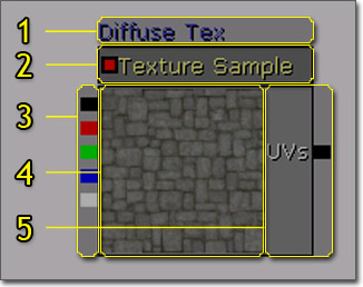
- Description - All materials expressions have a common Desc property. Text entered in this property will be displayed in the Material Editor just above the expression in the workspace. It can be used for any purpose, but usually serves as a good way to leave short notes about the purpose or function of the expression.
- Title bar - Displays the name and/or pertinent information about properties of the material expression.
- Outputs - Links that output the results of the material expression operation.
- Preview - Displays a preview of the value(s) that are output by the material expression. Updates automatically when realtime update is enabled. Can be manually updated using the Spacebar.
- Inputs - Links that take in the value(s) to be used by the material expression.
Abs
Abs is an abbreviation for the mathematical term "absolute value". The Abs expression outputs the absolute, or unsigned, value of the input it receives. Essentially, this means it turns negative numbers into positive numbers by dropping the minus sign, while positive numbers and zero remain unchanged. Examples: Abs of -0.7 is 0.7; Abs of -1.0 is 1.0; Abs of 1.0 is also 1.0 Example Usage: Abs is commonly used with DotProduct. DotProduct goes from -1..0..1, while taking the Abs of DotProduct will go from 1..0..1.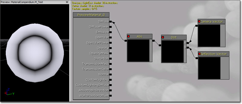
Add
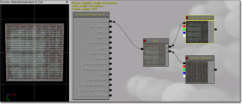
The Add expression takes two inputs, adds them together and outputs the result. This addition operation is performed on a per channel basis, meaning that the inputs' R channels get added, G channels get added, B channels get added, etc. Both inputs must have the same number of channels unless one of them is a single Constant value. Constants can be added to a vector with any number of inputs. Inputs- A - Takes in the value(s) to add to.
- B - Takes in the value(s) to be added.
AntialiasedTextureMask
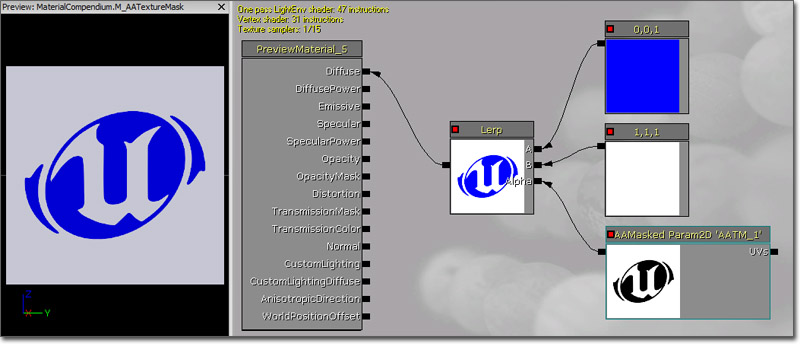
The AntialiasedTextureMask expression allows you to create a material using a soft (anti-aliased) transition mask. The mask can be used to blend between two complex material properties or to fade out a alpha blended material (works well with SoftMasked). Simple specify a texture with the mask specified in one channel (red, green, blue or alpha), set the used channel in the expression and specify the comparison value. Assuming the channel stores a grayscale value in the range 0=black to 1=white the comparison function defines if the resulting mask should be 0 or 1. This expression is a parameter, allowing the Texture property to be overridden by child MaterialInstances. Properties- Threshold - Specifies the value used as the cutoff point in pixel coverage. Pixel coverage values less than this become black; values greater become white.
- Channel - Specifies the channel of the Texture to use as the mask.
- Texture - Specifies the mask texture to use.
- UVs - Takes in texture coordinates to apply to the texture mask.
Result = 1
if TextureLookup < Threshold then Result = 0
The actual implementation is quite a bit more complicated as it tries to return values between 0 and 1 depending on the actual pixel coverage to avoid aliasing. Example (this tiny 128x128 texture, uncompressed for best quality): https://udn.epicgames.com/pub/Three/MaterialsCompendium/ULogoLowBlurred.bmp Was used as a normal texture (left top) and used with the described material expression (bottom right):
 The technique works best in magnification and with blurred input content. Compressed hurts the quality a lot so try to use uncompressed low resolution textures.
 See ImprovingAlphaTestWithAntiAliasing for implementation details.
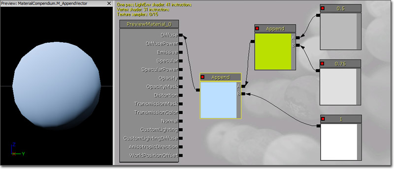
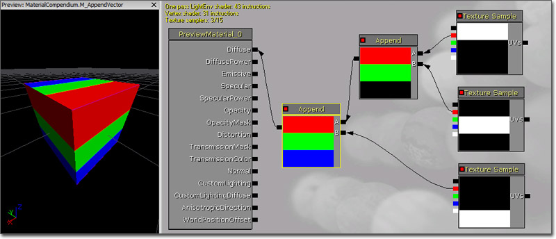
AppendVector
The AppendVector expression allows you to combine channels together to create a vector with more channels than the original. For example, you can take two individual Constants values and append them to make a two-channel Constant2Vector value. This can be useful for reordering the channels within a single texture or for combining multiple grayscale textures into one RGB color texture. Inputs- A - Takes in the value(s) to append to.
- B - Takes in the value(s) to be appended.
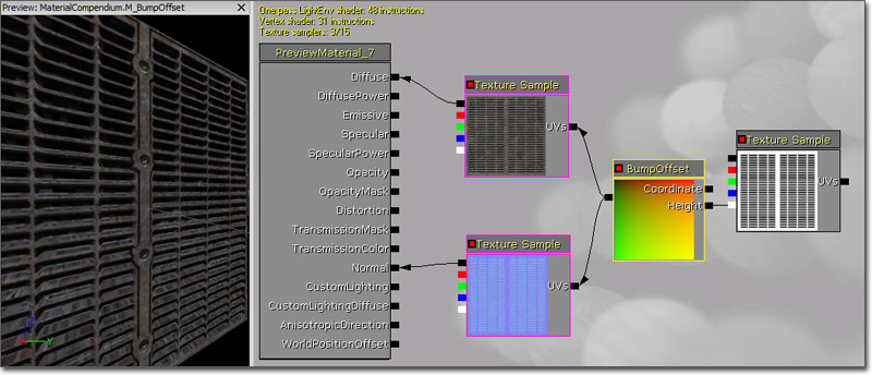
BumpOffset
BumpOffset is the Unreal Engine 3 term for what is commonly known as 'parallax mapping'. The BumpOffset expression allows a material to give the illusion of depth without the need for additional geometry. BumpOffset materials use a grayscale heightmap to give depth information. The brighter the value in the heightmap, the more 'popped out' the material will be; these areas will parallax (shift) as a camera moves across the surface. Darker areas in the heightmap are 'further away' and will shift the least. Properties- HeightRatio - Multiplier for the depth taken from the heightmap. The larger the value, the more extreme the depth will be. Typical values range from 0.02 to 0.1.
- ReferencePlane - Specifies the approximate height in texture space to apply the effect. A value of 0 will appear to distort the texture completely off the surface, whereas a value of 0.5 (the default) means that some of the surface will pop off while some areas will be sunken in.
- Coordinate - Takes in base texture coordinates to be modified by the expression.
- Height - Takes in the texture (or a value) to be used as the heightmap.
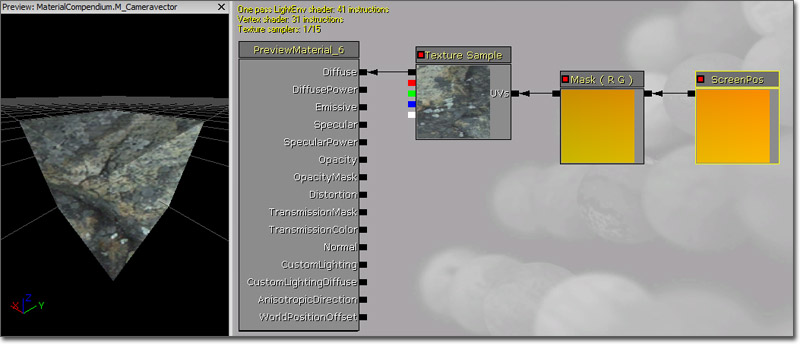
CameraVector
The CameraVector expression outputs a three-channel vector value representing the direction of the camera with respect to the surface, in other words, the direction from the pixel to the camera. Example Usage: CameraVector is often used to fake environment maps by connecting the CameraVector to a ComponentMask and use the x and y channels of the CameraVector as texture coordinates. (Hover for animated preview)
CameraWorldPosition
The CameraWorldPosition expression outputs a three-channel vector value representing the camera's position in world space. The preview sphere changes color as the camera rotates.
Ceil
The Ceil expression takes in value(s), rounds them up to the next integer, and outputs the result. See also Floor and Frac. Examples: Ceil of 0.2 is 1.0; Ceil of (0.2,1.6) is (1.0,2.0).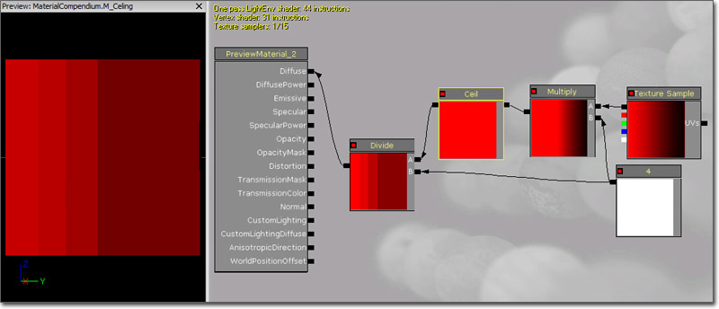
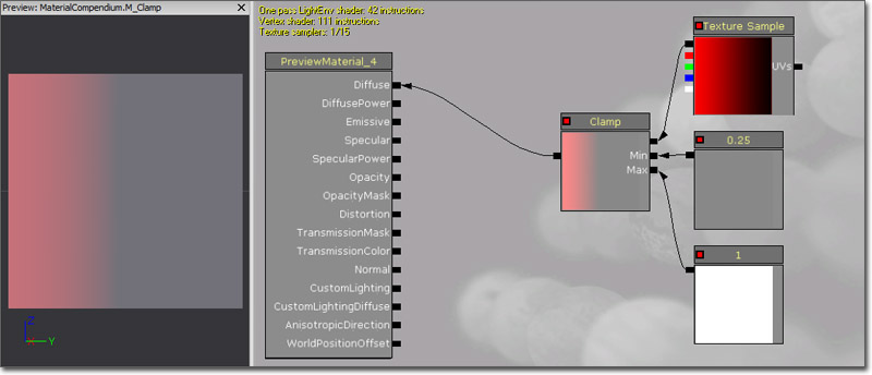
Clamp
The Clamp expression takes in value(s) and constrains them to a specified range, defined by a minimum and maximum value. A minimum value of 0.0 and maximum value of 0.5 means that the resulting value(s) will never be less than 0.0 and never greater than 0.5. Inputs- Min - Takes in the value to use as the minimum when clamping.
- Max - Takes in the value to use as the maximum when clamping.
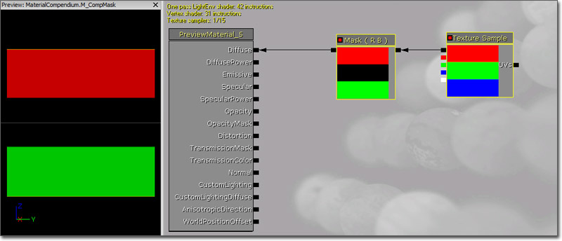
ComponentMask
The ComponentMask expression allows you to select a specific subset of channels (R, G, B, and/or A) from the input to pass through to the output. Attempting to pass a channel through that does not exist in the input will cause an error, unless the input is a single constant value. In that case, the single value is passed through to each channel. The current channels selected to be passed through are displayed in the title bar of the expression. Properties- R - If checked, the red, or first, channel of the input value will be passed through to the output.
- G - If checked, the green, or second, channel of the input value will be passed through to the output.
- B - If checked, the blue, or third, channel of the input value will be passed through to the output.
- A - If checked, the alpha, or fourth, channel of the input value will be passed through to the output.
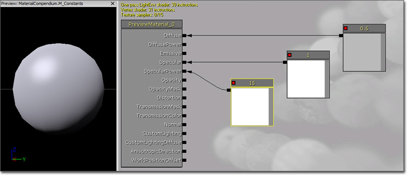
Constant
The Constant expression outputs a single float value. It is one the most commonly used expressions and can be connected to any input, regardless of the number of channels the input expects. Properties- R - Specifies the float value the expression outputs.
Constant2Vector
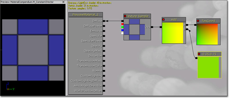
The Constant2Vector expression outputs a two-channel vector value, in other words, two constants numbers. Properties- R - Specifies the float value of the red, or first, channel of the vector the expression outputs.
- G - Specifies the float value of the green, or second, channel of the vector the expression outputs.
Constant3Vector
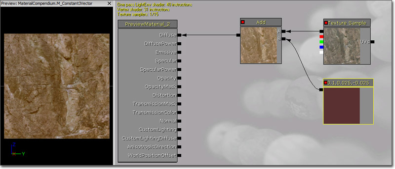
The Constant3Vector expression outputs a three-channel vector value, in other words, three constants numbers. An RGB color can be thought of as a Constant3Vector, where each channel is assigned to a color (red, green, blue). Properties- R - Specifies the float value of the red, or first, channel of the vector the expression outputs.
- G - Specifies the float value of the green, or second, channel of the vector the expression outputs.
- B - Specifies the float value of the blue, or third, channel of the vector the expression outputs.
Constant4Vector
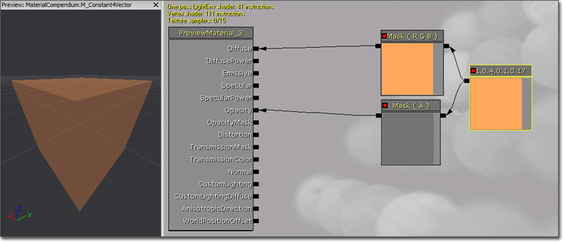
The Constant4Vector expression outputs a four-channel vector value, in other words, four constants numbers. An RGBA color can be thought of as a Constant4Vector, where each channel is assigned to a color (red, green, blue, alpha). Properties- R - Specifies the float value of the red, or first, channel of the vector the expression outputs.
- G - Specifies the float value of the green, or second, channel of the vector the expression outputs.
- B - Specifies the float value of the blue, or third, channel of the vector the expression outputs.
- A - Specifies the float value of the alpha, or fourth, channel of the vector the expression outputs.
ConstantBiasScale
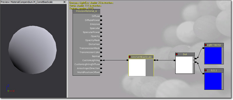
The ConstantBiasScale expression takes an input value, adds a bias value to it, and then multiplies it by a scaling factor outputting the result. So for example, to convert input data from [-1,1] to [0,1] you would use a bias of 1.0 and a scale of 0.5. Properties- Bias - Specifies the value to be added to the input.
- Scale - Specifies the multiplier for the biased result.
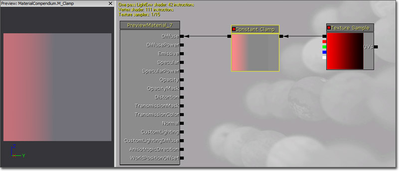
ConstantClamp
The ConstantClamp expression performs the same function as Clamp but uses properties for the minimum and maximum values in the node itself for simplicity and ease of use. This expression works well when you have min and max clamp values (say clamping an output from 0 to 1) that do not need to be variable over time. Properties- Min - Specifies the value to use as the minimum when clamping.
- Max - Specifies the value to use as the maximum when clamping.
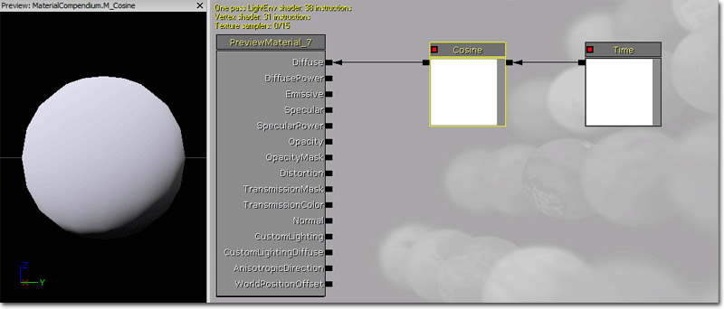
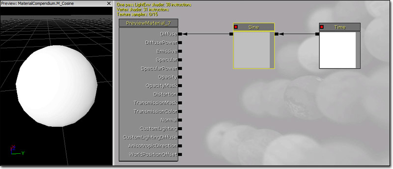
Cosine
The Cosine expression outputs the cosine of the value input (in radians). Most commonly, this is used to output a continuous oscillating waveform by connecting a Time expression to its input. The output value will cycle back and forth between -1 and 1. A visual representation of the wave is shown below: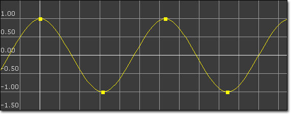 Properties
- Period - Specifies the period of the resultant wave. In other words, this is how long one oscillation takes to occur.
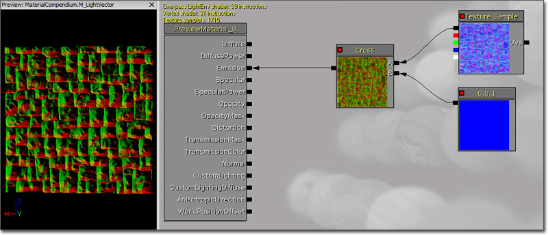
CrossProduct
The CrossProduct expression computes the cross product of two three-channel vector value inputs and outputs the resulting three-channel vector value. Given two lines (or vectors) in space, the cross product is a line (or vector) which is perpendicular to both of the inputs. Inputs- A - Takes in a three-channel vector value.
- B - Takes in a three-channel vector value.
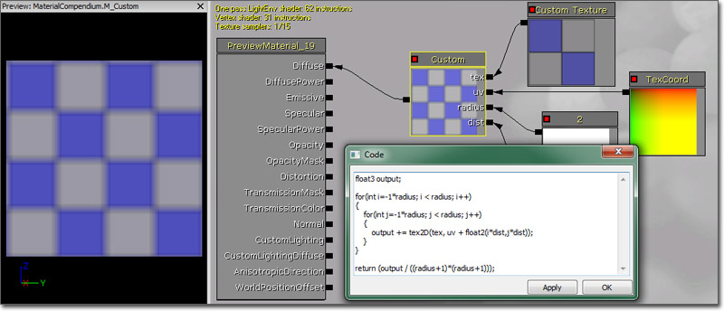
Custom
The Custom expression allows you to write custom HLSL shader code operating on an arbitrary amount of inputs and outputting the result of the operation. Warning! Using the custom node prevents constant folding and may use significantly more instructions than an equivalent version done with built in nodes! Constant folding is an optimization that UE3 employs under the hood to reduce shader instruction count when necessary. For example, an expression chain of 'Time->Sin->Mul by parameter->Add to something' can and will be collapsed by UE3 into a single instruction, the final add. This is possible because all of the inputs of that expression (Time, parameter) are constant for the whole draw call, they do not change per-pixel. UE3 cannot collapse anything in a custom node, which can produce less efficient shaders than an equivalent version made out of existing nodes. As a result, it's best to only use the custom node when it gives you access to functionality not possible with the existing nodes. Another Warning: shader code written in a custom node is compiled 'as is' for the target platform. This means that if the shader is being compiled for PC, it is assumed to be valid HLSL. If compiling for PS3, it is assumed to be valid Cg. Properties- Code - Contains the HLSL code the expression will execute.
- Output Type - Specifies the type of the value output by the expression.
- Description - Specifies the text to display in the title bar of the expression in the Material Editor.
- Inputs - The array of inputs used by the expression.
- Input Name - Specifies the name of the input. This is the name displayed on the expression in the Material Editor as well as the name used within the HLSL code to reference the input's value.
CustomTexture
The CustomTexture expression allows you to refer to a texture in the HLSL code inside a Custom expression, typically to sample it inside the HLSL using the tex2D or similar function. It's possible to use a regular TextureSample as input to a Custom node, but in that case the sample is being calculated outside the Custom node and the result passed in as a float4 value. This is not flexible enough for the case where you would like to sample the same texture multiple times in a loop, or to use other sampling instructions such as tex2Dbias, tex2Dlod, tex2Dproj (see HLSL documentation for the purpose of these).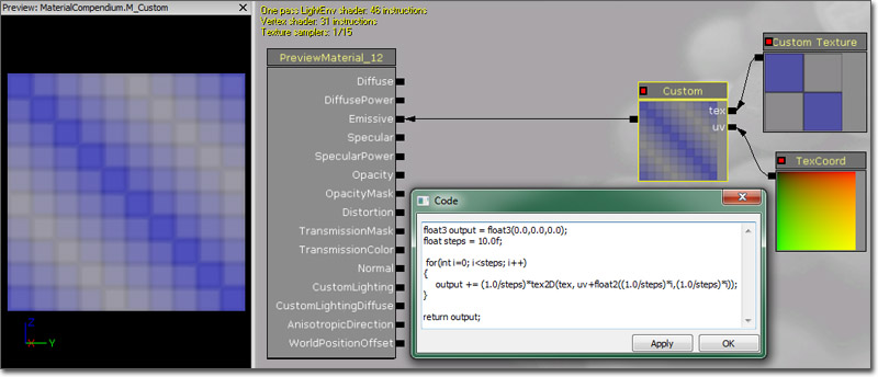
DepthBiasBlend
The DepthBiasBlend expression is most commonly used in materials on sprite particles to remove the sharp edges occurring when the sprite intersects other geometry. Depth-biased blending compares the depth of src and dst pixels and uses a bias to determine the alpha to use for drawing the pixel. See DepthBiasBlendUsage for more information. The DepthBiasBlend expression is slower and less flexible than the other depth-biased blending nodes; use DepthBiasAlpha instead. Programmers: DepthBiasBlend is the least preferred of the depth-biased blending nodes because 1) it samples color and depth from the most recent frame/depthbuffer resolves (slow); 2) the blend is performed in shader code rather than via hardware blending (slow); and 3) DepthBiasBlend's texture input is via the Texture property rather than an arbitrary expression input.DepthBiasAlpha
The DepthBiasAlpha expression is most commonly used in materials on sprite particles to remove the sharp edges occurring when the sprite intersects other geometry. Depth-biased blending compares the depth of src and dst pixels and uses a bias to determine the alpha to use for drawing the pixel. See DepthBiasBlendUsage for more information. The DepthBiasAlpha expression is the preferred node to use for depth-biased blending.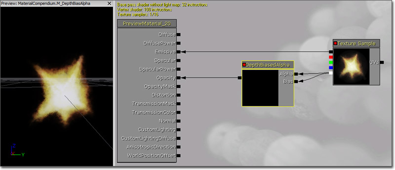 Programmers: DepthBiasAlpha is the preferred way to do depth-biased blending because the blend is performed in hardware rather than in the shader.
DepthBiasedBlend
The DepthBiasedBlend expression is most commonly used in materials on sprite particles to remove the sharp edges occurring when the sprite intersects other geometry. Depth-biased blending compares the depth of src and dst pixels and uses a bias to determine the alpha to use for drawing the pixel. See DepthBiasBlendUsage for more information. The DepthBiasedBlend expression is slower than DepthBiasAlpha; use DepthBiasAlpha instead. Programmers: DepthBiasedBlend is the least preferred of the depth-biased blending nodes because 1) it samples color and depth from the most recent frame/depthbuffer resolves (slow); and 2) the blend is performed in shader code rather than via hardware blending (slow).DeriveNormalZ
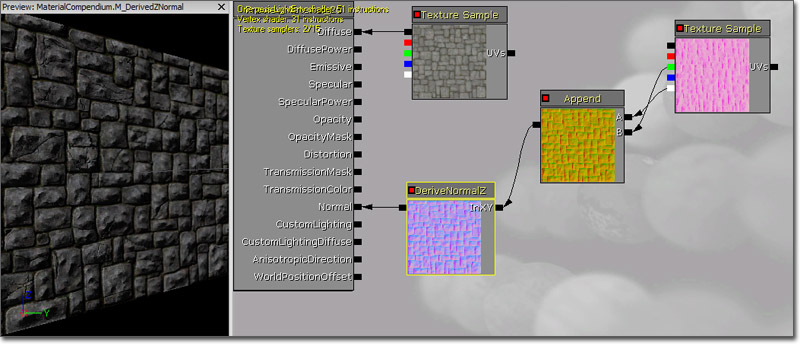
The DeriveNormalZ expression derives the Z component of a tangent space normal given the X and Y components and outputs the resulting three-channel tangent space normal. Z is calculated as Z = sqrt(1 - (x * x + y * y)); Inputs- InXY - Takes in the X and Y components of the tangent space normal in the form of a two-channel vector value.
Desaturation
The Desaturation expression desaturates its input, or converts the colors of its input into shades of gray, based a certain percentage. Properties- Luminance Factors - Specifies the amount that each channel contributes to the desaturated color. This is what controls that green is brighter than red which is brighter than blue when desaturated.
- Percent - Specifies the amount of desaturation to apply to the input. Percent can range from 0.0 (fully desaturated) to 1.0 (full original color, no desaturation).
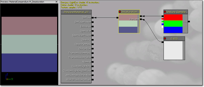 Programmers: Define desaturated color D, input color I and luminance factor L. The output will be O = (1-Percent)*(D.dot(I)) + Percent*I
DestColor
The DestColor expression outputs the existing color of the rendered scene in its current state behind the pixel currently being drawn. Example Usage: A water material can use DestColor to sample the color of the rocks under the water.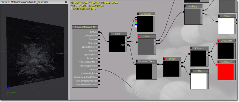
DestDepth
The DestDepth expression outputs the existing depth of the rendered scene in its current state behind the pixel currently being drawn. Example Usage: A water material can use DestDepth to give water a "thickness" or fog color, where the deeper the water (the greater the depth), the more the water obscures the rocks under the water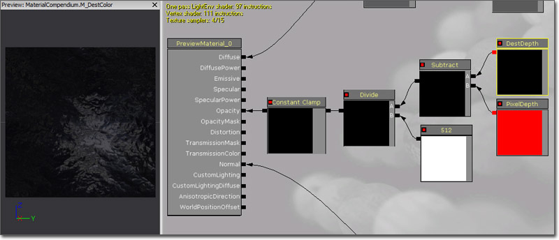 Programmers: DestDepth returns a raw depth value (integer from 0 to 2^24-1). This non-leaner depth can be normalized as follows:
   MaxZ = 16777215
   NormalizedDepth = 1 - MaxZ / (DestDepth + MaxZ)
The resulting normalized depth is linear in the 0.0 to 1.0 range.
Distance
The Distance expression computes the (Euclidian) distance between two points/colors/positions/vectors and outputs the resulting value. This works on one, two, three and four component vectors, but both inputs to the expression must have the same number of channels. Inputs- A - Takes in a value or vector of any length.
- B - Takes in a value or vector of any length.
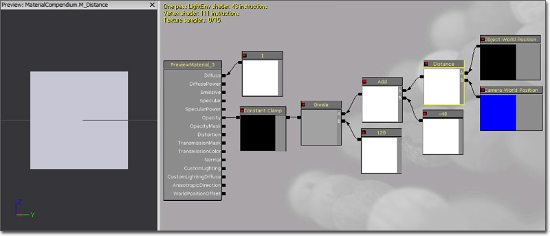 Pseudo code: Result = length(A - B)
Low level HLSL code: float Result = sqrt(dot(A-B, A-B))
Pseudo code: Result = length(A - B)
Low level HLSL code: float Result = sqrt(dot(A-B, A-B))
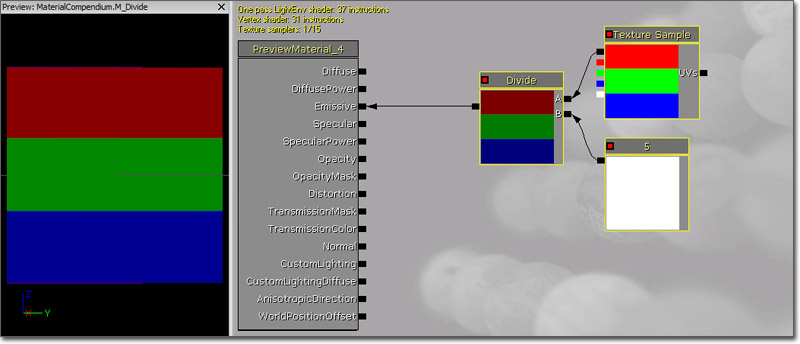
Divide
The Divide expression takes two inputs and outputs the result of the first divided by the second. The division happens per channel, meaning that the R channel of the first is divided by the second, the G channel of the first is divided by the second, and so on. Both inputs must have the same number of values unless the divisor is a single float value. Inputs- A - Takes in the value(s) to be divided, the dividend.
- B - Takes in the value(s) to divide by, the divisor.
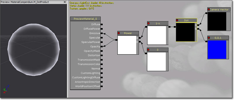
DotProduct
The DotProduct expression computes the dot product, or the length of one vector projected onto the other. This calculation is used by many techniques for computing falloff. DotProduct requires both vector inputs to have the same number of channels. Inputs- A - Takes in a value or vector of any length.
- B - Takes in a value or vector of any length.
DynamicParameter
The DynamicParameter expression provides a conduit for particle emitters to pass up to four values to the material to be used in any manner. These values are set in Cascade via a ParameterDynamic module placed on an emitter. Properties- Param Names - An array of the names of the parameters. The values here will determine the text displayed on the outputs of the expression in the Material Editor and will be the names used to reference the parameters in the ParameterDynamic module in Cascade.
- Param1 - Outputs the value of the first parameter in the Param names property. The name of this output can change based on the values in the Param Names property.
- Param2 - Outputs the value of the second parameter in the Param names property. The name of this output can change based on the values in the Param Names property.
- Param3 - Outputs the value of the third parameter in the Param names property. The name of this output can change based on the values in the Param Names property.
- Param4 - Outputs the value of the fourth parameter in the Param names property. The name of this output can change based on the values in the Param Names property.
FlipBookSample
The FlipBookSample expression enables an animated flipbook texture to be used in a material. This is very similar to a TextureSample, but textures that were imported as flipbook texture need to use a FlipBookSample expression as under the hood, FlipBookSample performs the necessary UV manipulation to render the subimages of a flipbook texture, based on the HorizontalImages, VerticalImages and FrameRate properties of the flipbook texture. Properties- Texture - Specifies the flipbook texture to use.
- UVs - Takes in texture coordinates to apply to the texture.

Floor
The Floor expression takes in value(s), rounds them down to the previous integer, and outputs the result. See also Ceil and Frac. Examples: Floor of 0.2 is 0.0; Floor of (0.2,1.6) is (0.0, 1.0).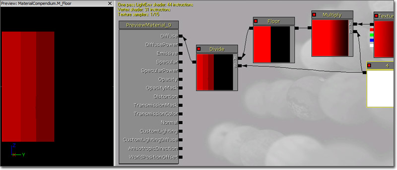
FluidNormal
The FluidNormal expressions provides access to the normal map generated by a FluidSurfaceActor, containing all the turbulence, including ripples and waves, caused from objects interacting dynamically with the fluid surface. This can be used in conjunction with other normal maps to create ambient turbulence in addition to the interactive turbulence calculated by the fluid surface.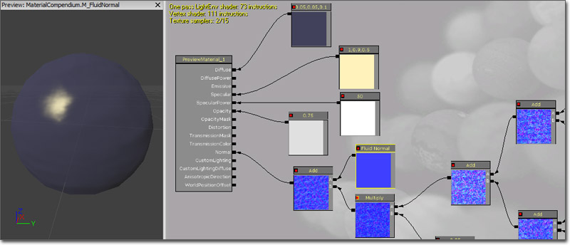
FMod
The FMod expression returns the floating-point remainder of the division operation of the two inputs. (Hover for animated preview)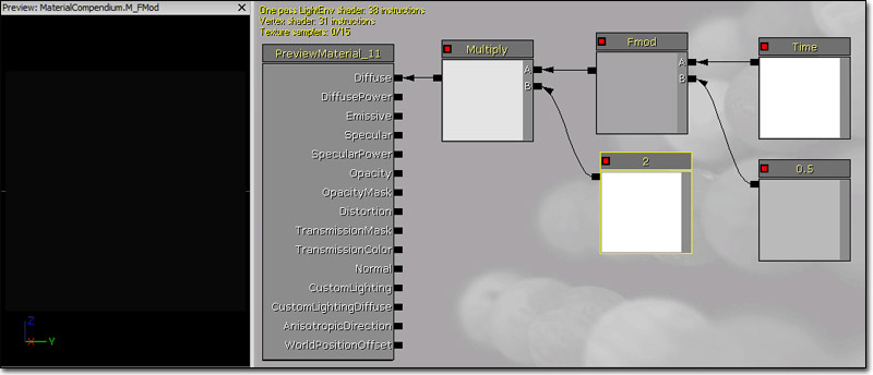
FoliageNormalizedRotationAxisAndAngle
This FoliageNormalizedRotationAxisAndAngle expression is designed to be used in conjunction with RotateAboutAxis, and the value is automatically set by code when the material is applied to a InteractiveFoliageActor. RGB contains the normalized axis to rotate about in order to apply the InteractiveFoliageActor spring offset. Alpha contains the angle, in radians, of the rotation to apply the spring offset. See InteractiveFoliageActor for an example.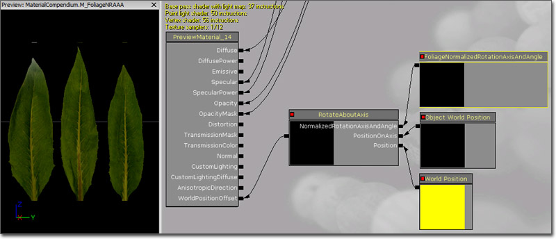
FoliageImpulseDirection
The FoliageImpulseDirection expression's output value is automatically set by code when the material is applied to a InteractiveFoliageActor, and it provides raw access to the InteractiveFoliageActor spring offset. See InteractiveFoliageActor for an example.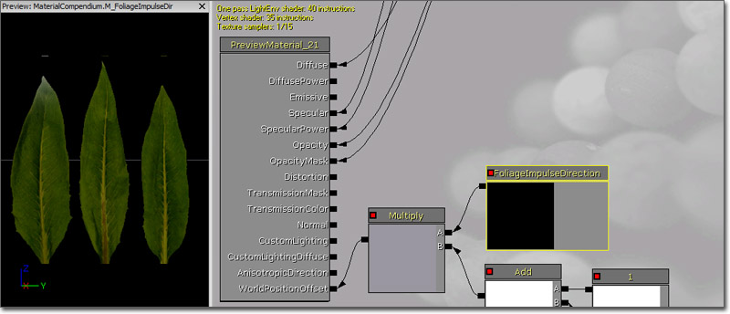
FontSampler
The FontSampler expression allows you to sample the texture pages out of a font resource as regular 2D textures. The alpha channel of the font will contain the font outline value. Only valid font pages are allowed to be specified.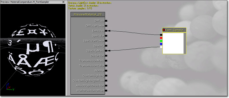
Frac
The Frac expression takes in value(s) and outputs the decimal part of those values. See also Ceil and Floor. Examples: Frac of 0.2 is 0.2; Frac of (0.0,1.6) is (0.0, 0.6)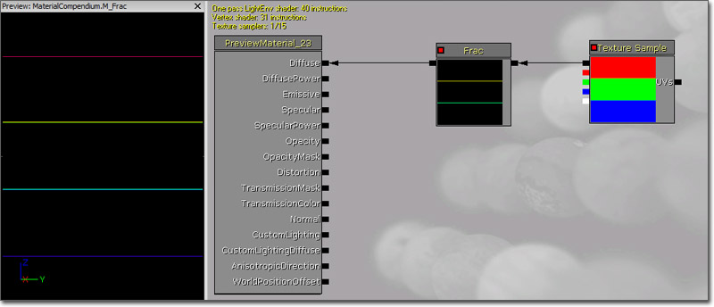
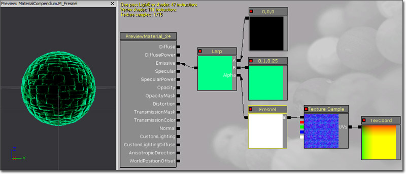
Fresnel
The Fresnel expression calculates a falloff based on the dot product of the surface normal and the direction to the camera. When the surface normal points directly at the camera, a value of 0 is output. When the surface normal is perpendicular to the camera, a value of 1 is output. The result is clamped to [0,1] so you don't have any negative color in the center. Properties- Exponent - Specifies the how quickly the output value falls off. Larger values mean tighter or quicker falloff.
- Normal - Takes in a three-channel vector value representing the normal of the surface, usually a normal map. If no normal is specified, the tangent normal of the mesh is used.
FunctionInput
The FunctionInput expression can only be placed in a material function, where it defines one of the function's inputs. Properties- Input Name - The input's name, which will be displayed on MaterialFunctionCall expressions that use the material function containing the input.
- Description - A description of the input, which will be displayed as a tooltip when the connector for this input on a MaterialFunction Call expression is hovered over with the mouse.
- Input Type - The type of data this input expects. Data passed to this input will be cast to this type, throwing a compiler error if the cast fails because the data is not compatible.
- Preview Value - The value to use as a preview for this input when editing the material function containing it.
- Use Preview Value As Default - If enabled, the Preview Value will be used as the default value for this input if no data is passed in.
- Sort Priority - Specifies the priority for this input to use when determining the order of the inputs to be displayed on a MaterialFunctionCall expression.
FunctionOutput
The FunctionInput expression can only be placed in a material function, where it defines one of the function's outputs. Properties- Output Name - The output's name, which will be displayed on MaterialFunctionCall expressions that use the material function containing the output.
- Description - A description of the output, which will be displayed as a tooltip when the connector for this output on a MaterialFunction Call expression is hovered over with the mouse.
- Sort Priority - Specifies the priority for this output to use when determining the order of the outputs to be displayed on a MaterialFunctionCall expression.
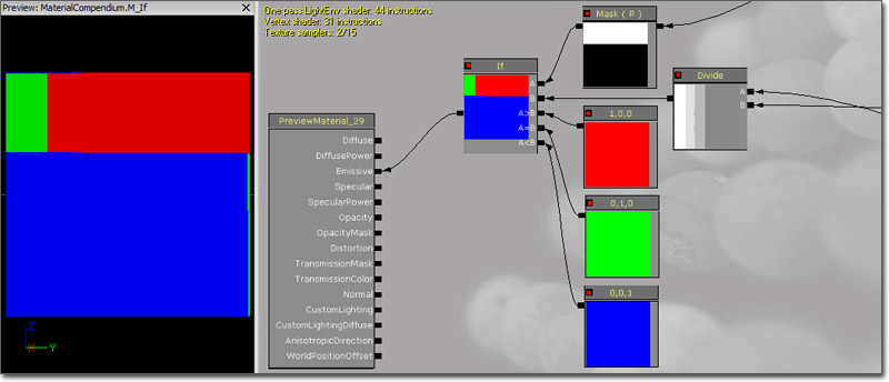
If
The If expression compares two inputs and then passes through one of three other input values based on the result of the comparison. The two inputs to be compared must be single float values. Inputs- A - Takes in a single float value.
- B - Takes in a single float value.
- A>B - Takes in the value(s) to output if the value of A is greater than the value of B.
- A=B - Takes in the value(s) to output if the value of A is equal to the value of B.
- A<B - Takes in the value(s) to output if the value of A is less than the value of B.
LensFlareIntensity
The LensFlareIntensity expression provides the 'ConeStrength' of a lens flare that is rendering. The cone strength is provided to allow for determining the intensity of the flare with respect to the position of the view in relation to the flare source. The cone strength will be 0.0 if the flare source is located outside of the radius of the lens flare. (If the radius of the lens flare is set to 0.0f, then it is considered to be always on.) If it is inside the radius, it will be 1.0f. If the lens flare is setup with a directional cone, the ConeStrength will be 1.0f if the view is located in the inner cone and looking towards the flare. It will fall off to 0.0f when moving through the outer cone.LensFlareOcclusion
The LensFlareOcclusion expression provides the occlusion value of a lens flare that is rendering. The value is determined by the primitive coverage percentage being used as the look-up value into the ScreenPercentageMap of the lens flare.LensFlareRadialDistance
The LensFlareRadialDistance expression provides the radial distance of the element being rendered from the center of the screen. This value can be normalized to be a 0.0f (center) to 1.0f (edge) value using the bNormalizeRadialDistance property of the lens flare element. Otherwise, the value will typically be in the 0.0f (center) to 1.0f (vertical or horizontal edge) to 1.4f (corner of the screen). The 1.4f will be the ratio of the screen width and height.LensFlareRayDistance
The LensFlareRayDistance expression provides the ray distance that is set for the flare element that is being rendered.LensFlareSourceDistance
The LensFlareSourceDistance expression provides the distance of the element being rendered from the source in screen space.LightmapUVs
The LightmapUVs expression outputs the lightmap UV texture coordinates in the forum of a two-channel vector value. If lightmap UVs are unavailable, it will output a two-channel vector value of (0,0).LightmassReplace
The LightmassReplace expression simply passes through the Realtime input when compiling the material for normal rendering purposes, and passes through the Lightmass input when exporting the material to Lightmass for global illumination. This is useful to workaround material expressions that the exported version can't handle correctly, for example WorldPosition. Inputs- Realtime - Takes in the value(s) to pass through for normal rendering.
- Lightmass - Takes in the value(s) to pass through when exporting the material to Lightmass.
LightVector
The LightVector expression is a three-channel vector value representing the direction of the light with respect to the surface. Example Usage: LightVector can be used to calculate custom lighting algorithms, such as a simple Lambert lighting model.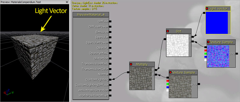
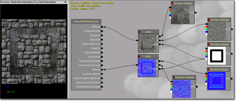
LinearInterpolate
The LinearInterpolate expression blends between two input value(s) based on a third input value used as a mask. This can be thought of as a mask to define transitions between two textures, like a layer mask in Photoshop. The intensity of the mask Alpha determines the ratio of color to take from the two input values. If Alpha is 1.0/white, the first input is used. If Alpha is 0.0/black, the second input is used. If Alpha is grey (somewhere between 0.0 and 1.0), the output is a blend between the two inputs. Keep in mind that the blend happens per channel. So, if Alpha is an RGB color, Alpha's red channel value defines the blend between A and B's red channels independently of Alpha's green channel, which defines the blend between A and B's green channels. Inputs- A - Takes in the value(s) mapped to white.
- B - Takes in the value(s) mapped to black.
- Alpha - Takes in the value to use as the mask alpha.
MaterialFunctionCall
The MaterialFuntionCall expression allows you to use an external MaterialFunction from another material or function. The external function's input and output nodes become inputs and outputs of the function call node. If a MaterialFunction is selected int he Content Browser when placing one of these expressions, it will automatically be assigned. Shortcut: F + Left Mouse Click Properties- Material Function - Specifies the MaterialFunction to be used.
MeshEmitterDynamicParameter
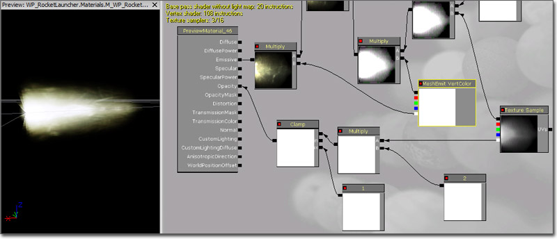
The MeshEmitterDynamicParameter expression is identical to the standard DynamicParameter except that is must be used if the material is being used with a mesh emitter in Cascade. It provides the same four outputs for passing values from Cascade to the material.MeshEmitterVertexColor
The MeshEmitterVertexColor expression is the access point for the material to the outputs of color modules affecting mesh particles emitters. Each mesh rendered as a particle by a mesh emitter has a color available to it -- this is that color. Outputs- RGB - Outputs the three-channel RGB vector value of the color.
- R - Outputs the red channel of the color.
- G - outputs the green channel of the color.
- B - Outputs the blue channel of the color.
- A - Outputs the alpha channel of the color.
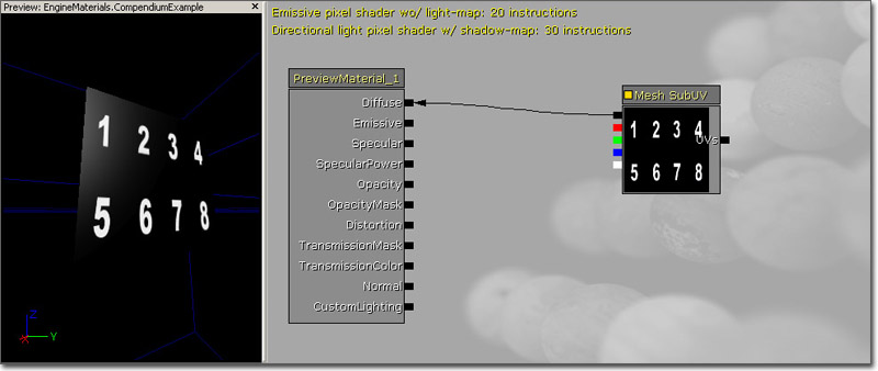
MeshSubUV
The MeshSubUV expression is identical to the ParticleSubUV except that is must be used when the material is being used with a mesh emitter in Cascade. It provides the same ability to display a subimage from the texture applied to the expression, but it lacks the ability to blend between subimages. This expression needs to be used in place of the standard ParticleSubUV to avoid repacking the texture coordinates for a mesh particle every frame. Properties- Texture - Specifies the texture to use.
- UVs - The UV input is ignored and does nothing.
MeshSubUVBlend
The MeshSubUVBlend expression is identical to the MeshSubUV except that it provides the ability to blend between the subimages when using the linear blend or random blend modes in Cascade. Properties- Texture - Specifies the texture to use.
- UVs - The UV input is ignored and does nothing.
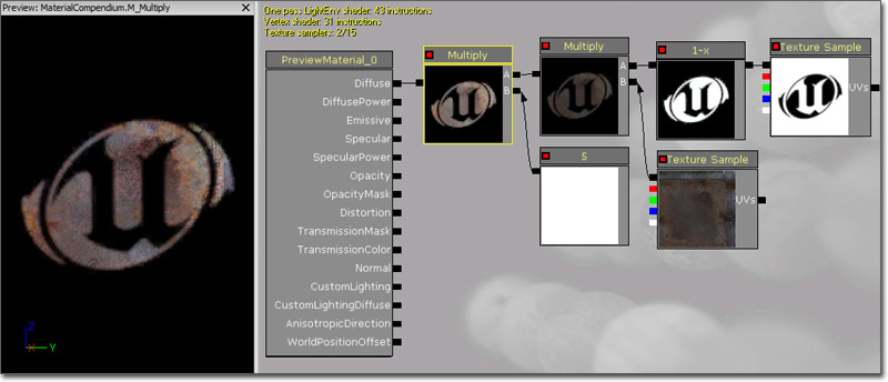
Multiply
The Multiply expression takes two inputs, multiplies them together, and outputs the result. Similar to Photoshop's multiply layer blend. The multiplication happens per channel, meaning that the R channel of the first is multiplied by the second; the G channel of the first is multiplied by the second, and so on. Both inputs must have the same number of values unless one of the values is a single float value. Inputs- A - Takes in the first value(s) to multiply.
- B - Takes in the second value(s) to multiply.
Normalize
The Normalize expression calculates and outputs the normalized value of its input. This means each component of the input is divided by the L-2 norm (length) of the vector.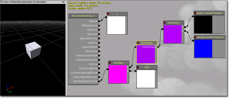
ObjectOrientation
The ObjectOrientation expression outputs the world-space up vector of the object. In other words, this is the direction the local positive Z-axis of the object the material is applied to is pointing.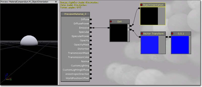
ObjectRadius
The ObjectRadius expression outputs the world-space radius of the object's bounds. You can preview the bounds of any object by enabling the 'show bounds' viewmode for the active viewport (under the down arrow at the top of the viewport), then selecting an object. See ObjectWorldPosition for an example.ObjectWorldPosition
The ObjectWorldPosition expression outputs the world-space center position of the object's bounds. This is useful for creating spherically lighting for foliage, for example. The node setup below is using object position, world position and object radius to make a gradient that has a value of 1 at object position, and 0 at the object radius.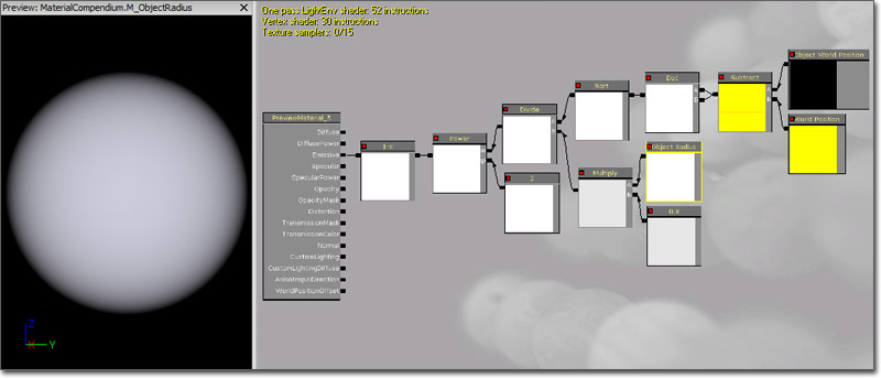
OcclusionPercentage
The OcclusionPercentage expression outputs the occlusion percentage of the object being rendered. Only used by ParticleSystems (that have OcclusionBoundMethod other than None) and by LensFlares.OneMinus
The OneMinus expression takes an input value and outputs one minus that value. This operation is performed per channel. Examples: OneMinus of 0.4 is 0.6; OneMinus of (0.2,0.5,1.0) is (0.8,0.5,0.0); OneMinus of (0.0,-0.4,1.6) is (1.0,1.4,-0.6) Example Usage: When the input colors are in the range [0,1], OneMinus has the same effect as what is commonly called "invert" -- that is, OneMinus returns the complimentary color that when added to the input will produce white.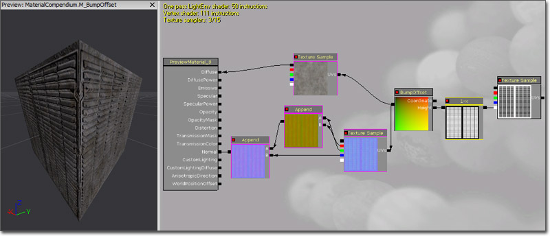
Panner
The Panner expression outputs UV texture coordinates that can be used to create panning, or moving, textures. Properties- SpeedX - Specifies the speed to pan the coordinates in the U direction.
- SpeedY - Specifies the speed to pan the coordinates in the V direction.
- Coordinate - Takes in base UV texture coordinates the expression can then modify.
- Time - Takes in a value used to determine the current panning position. This is usually a Time expression to provide a constant panning effect, but a Constant or ScalarParameter can be used as well to set a specific offset or to control the panning through Matinee or UnrealScript.

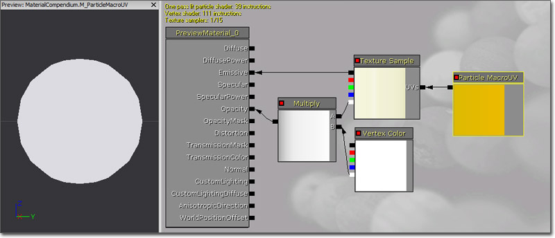
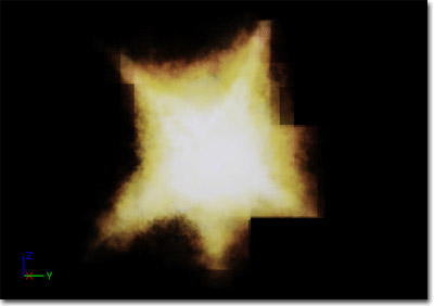
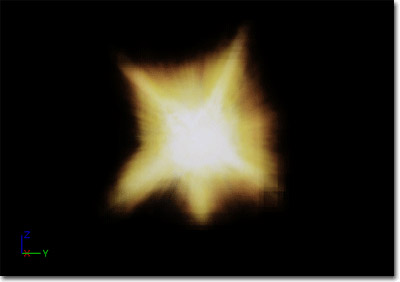
ParticleMacroUV
The ParticleMacroUV epxression outputs UV texture coordinates that can be used to map any 2d texture onto the entire particle system in a continuous way, meaning the texture will be seamless across particles. The UVs will be centered around MacroUVPosition (specified in Cascade on the ParticleSystem, under the MacroUV category) and MacroUVRadius determines the world space radius that the UVs should tile at. The ParticleMacroUV node is useful for mapping continuous noise onto particles to break up the pattern introduced by mapping a texture onto each particle with normal texture coordinates. Properties- Use View Space - If true, effectively offsets the coordinates based on the depth of each sprite and creates a parallax effect, which can be useful for giving explosions a radial blur look
 (Hover for animated preview)

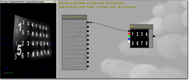
ParticleSubUV
The ParticleSubUV expression is used to render subimages of a texture to a particle. ParticleSubUV is similar to a flipbook, except that ParticleSubUV allows the texture animation to be manipulated in Cascade. Properties- Texture - Specifies the texture to use.
- UVs - The UV input is ignored and does nothing.
PerInstanceRandom
The PerInstanceRandom expression outputs a different random float value per static mesh instance to which the material is applied. InstancedStaticMeshComponent sets a random float for instance, which is exposed so that it can be used for whatever is desired (e.g. random light level behind a window). It is constant, but different, for each instance of the mesh. The output value will be a whole number between 0 and RAND_MAX for the target platform. Note: This only works when applied to an InstancedStaticMesh Actor or other Actor which ustilizes InstancedStaticMeshComponents, such as ProcBuildings.PixelDepth
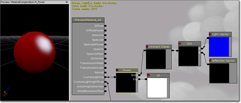
The PixelDepth expression outputs the depth, or distance from the camera, of the pixel currently being rendered. For details on using the value, consult DestDepth.Power
The Power expression takes two inputs, raises Base to the Exp power, and outputs the result; in other words, Base multiplied by itself Exp times. Inputs- Base - Takes in the base value.
- Exp - Takes in the exponent value.
ReflectionVector
The ReflectionVector expression is similar in spirit to CameraVector, but it outputs a three-channel vector value representing the camera direction reflected across the surface normal. Example Usage: ReflectionVector is commonly used in environment maps, where the x/y components of the reflection vector are used as UVs into a cubemap texture.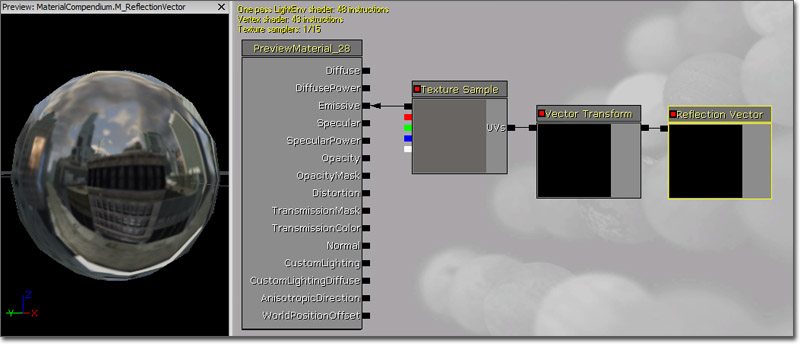
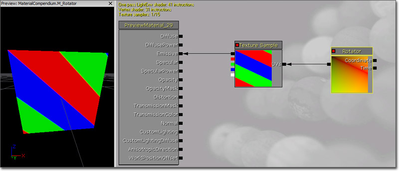
Rotator
The Rotator expression outputs UV texture coordinates in the form of a two-channel vector value that can be used to create rotating textures. Properties- CenterX - Specifies the U coordinate to use as the center of the rotation.
- CenterY - Specifies the V coordinate to use as the center of the rotation.
- Speed - Specifies the speed to rotate the coordinates clockwise.
- Coordinate - Takes in base UV texture coordinates the expression can then modify.
- Time - Takes in a value used to determine the current rotation position. This is usually a Time expression to provide a constant rotation effect, but a Constant or ScalarParameter can be used as well to set a specific offset or to control the rotation through Matinee or UnrealScript.
RotateAboutAxis
The RotateAboutAxis expression rotates a three-channel vector input given the rotation axis, a point on the axis, and the angle to rotate. It is useful for animations using WorldPositionOffset that have better quality than simple shears. See InteractiveFoliageActor for an example. Inputs- NormalizedRotationAxisAndAngle - Takes in the output of a FoliageNormalizedRotationAxisAndAngle expression.
- PositionOnAxis - Takes in the three-channel vector representing the position on the axis for the rotation to take place at.
- Position - Takes in the three-channel vector representing the position of the object.
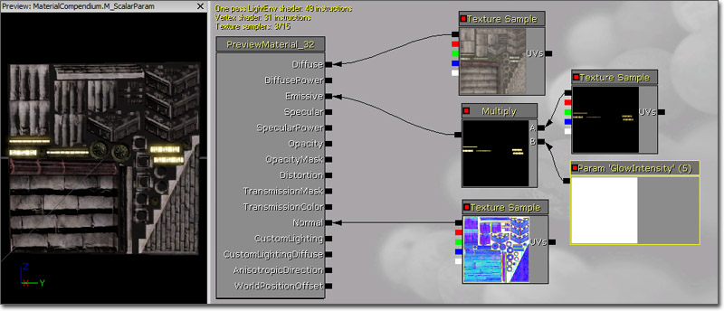
ScalarParameter
The ScalarParameter expression outputs a single float value (Constant) that can be accessed and changed in an instance of the material or on the fly by code. Properties- Default Value - Specifies the initial value that the constant takes on.
- Param Name - Specifies the name that is used to identify the parameter in an instance of the material or though code.
SceneDepth
The SceneDepth expression outputs the existing scene depth. This is similar to DestDepth, except that DestDepth can sample the depth only at the pixel currently being drawn, whereas SceneDepth can sample depth at any location. Properties- Normalize - If true, the depth output is normalized to a [0,1] range.
- UVs - Takes in UV texture coordinates used to determine how the depth "texture" is sampled.
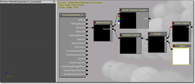
 Programmers: SceneDepth returns a raw depth value (integer from 0 to 2^24-1). This non-linear depth can be normalized as follows:
   MaxZ = 16777215
   NormalizedDepth = 1 - MaxZ / (SceneDepth + MaxZ)
The resulting normalized depth is linear in the 0.0 to 1.0 range.
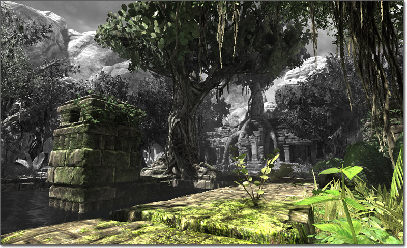
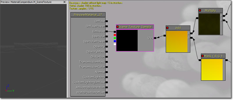
SceneTexture
The SceneTexture expression outputs the existing scene color. This is similar to DestColor, except that DestColor can sample the color only at the pixel currently being drawn, whereas SceneTexture can sample color at any location. Properties- Scene Texture Type -
- Screen Align - If true, maps the [0,1] UV texture coordinates to the current size of the back buffer; in other words, the scene texture is mapped to the screen one-to-one.
- UVs - Takes in UV texture coordinates used to determine how the scene texture is sampled.
ScreenPosition
The ScreenPosition expression outputs the screen-space position of the pixel currently being rendered. Properties- Screen Align - If true, ScreenPosition divides the position by the homogeneous coordinate and maps the position to [0,0] - [1,1] for screen alignment.
Sine
The Sine expression outputs the sine of the value input (in radians). Most commonly, this is used to output a continuous oscillating waveform by connecting a Time expression to its input. The output value will cycle back and forth between -1 and 1. The difference between this and the output of the Cosine expression is the output waveform is offset half the period. A visual representation of the wave is shown below: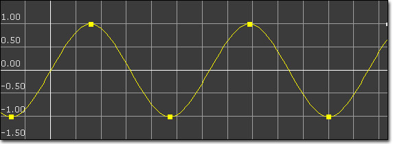 Properties
- Period - Specifies the period of the resultant wave. In other words, this is how long one oscillation takes to occur.

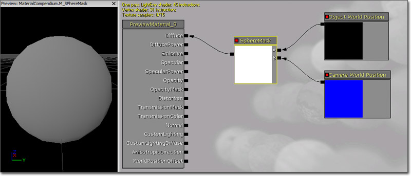
SphereMask
The SphereMask expression outputs a mask value based on a distance calculation. If one input is the position of a point and the other input is the center of a sphere with some radius, the mask value is 0 outside and 1 inside with some transition area. This works on one, two, three and four component vectors Properties- Attenuation Radius - Specifies the radius to use for the distance calculation.
- Hardness Percent - Specifies the transition area size. This works like the Photoshop brush hardness value. 0 means the transition is hard, 100 means the transition area is maximal(soft).
- A - Takes in the value representing the position of the point to check.
- B - Takes in the value representing the center of the sphere.
SquareRoot
The SquareRoot expression outputs the square root of the input value. SquareRoot can operate only on a single float input value.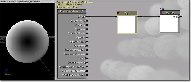
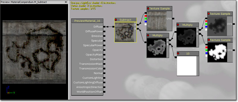
Subtract
The Subtract node takes in two inputs, subtracts the second input from the first, and outputs the difference. The subtraction happens per channel, meaning that the R channel of the second input gets subtracted from the first; the G channel of the second input gets subtracted from the first, and so on. Both inputs must have the same number of channels unless the second input is a single Constant value. Constants can be subtracted from a vector with any number of inputs. Inputs- A - Takes in the value(s) of the minuend.
- B - Takes in the value(s) to be subtrahend.
StaticBool
The StaticBool expression is used to provide a default bool value for a static bool function input within a function. This node does not switch between anything, so it must be used in conjunction with a StaticSwitch node. Properties- Value - The value of the bool, TRUE (checked) or False.
StaticBoolParameter
The StaticBoolParameter works like StaticSwitchParameter, except that it only creates a bool parameter and does not implement the switch. Properties- Default Value - The default bool value of the parameter, TRUE (checked) or False.
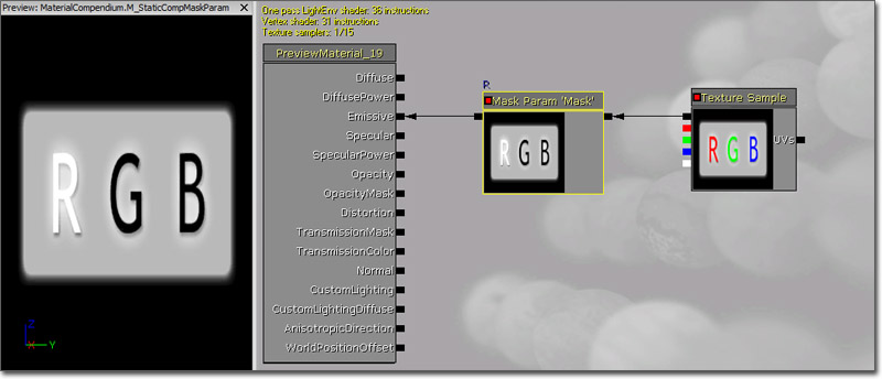
StaticComponentMaskParameter
The StaticComponentMaskParameter expression behaves just like an ordinary Component Mask, except that the mask values can be set by instances. It is static because it cannot change at runtime, it can only be set in the Material Instance Editor. Static Component Masks are applied at compile time, not at runtime. A new version of the material must be compiled out for every used combination of static parameters in a material, which can lead to a shader explosion if abused. Try to minimize the number of static parameters in the material and the number of permutations of those static parameters that are actually used. Properties- Default R - If checked, the red, or first, channel of the input value will be passed through to the output.
- Default G - If checked, the green, or second, channel of the input value will be passed through to the output.
- Default B - If checked, the blue, or third, channel of the input value will be passed through to the output.
- Default A - If checked, the alpha, or fourth, channel of the input value will be passed through to the output.
- Parameter Name - Specifies the name used to identify the parameter in instance of the material and through code.
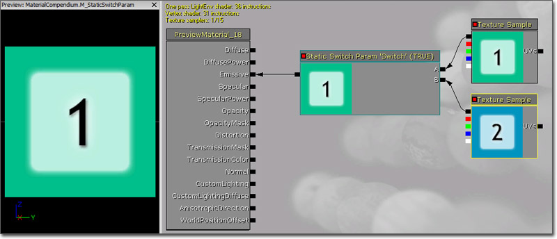
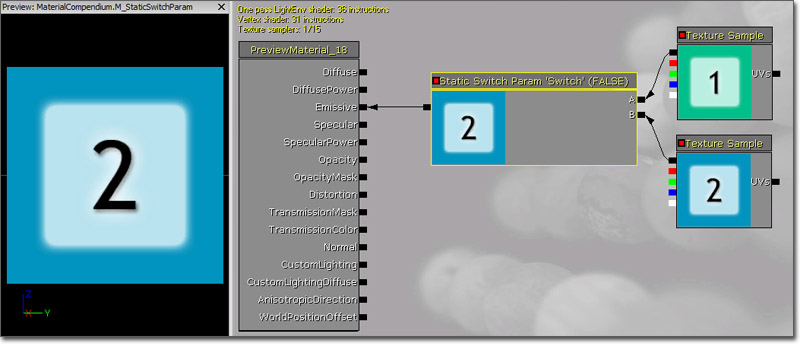
StaticSwitchParameter
The StaticSwitchParameter expression takes in two inputs, and outputs the first if the value of the parameter is true, and the second otherwise. This parameter is named static because it cannot change at runtime, it can only be set in the Material Instance Editor. Static Switches are applied at compile time, not at runtime. This means that whatever branch of the material was dropped will never be executed, so static switches are effectively free at runtime. On the other hand, a new version of the material must be compiled out for every used combination of static parameters in a material, which can lead to a shader explosion if abused. Try to minimize the number of static parameters in the material and the number of permutations of those static parameters that are actually used. Properties- Default Value - If true, the first input is output. Otherwise, the second input is output.
- Extended Caption Display - If true, the title bar of the expressions displays the value of the expression.
- Parameter Name - Specifies the name used to identify the parameter in instance of the material and through code.
- A - Takes in a value of any number of channels.
- B - Takes in a value of any number of channels.
StaticSwitch
The StaticSwitch expression works like a StaticSwitchParameter, except that it only implements the switch and does not create a parameter. Properties- Default Value - The default bool value of the parameter that determines which input is active, True (checked) or False.
- True - The input that is used when the Value of the wsitch is True.
- False - The input that is used when the Value of the wsitch is False.
- Value - Takes in a bool value that determines which input is active.
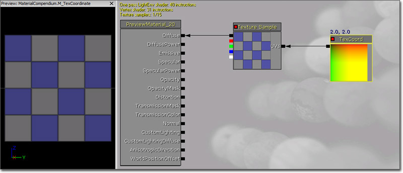
TextureCoordinate
The TextureCoordinate expression outputs UV texture coordinates in the form of a two-channel vector value allowing materials to use different UV channels, specify tiling, and otherwise operate on the UVs of a mesh. Properties- Coordinate Index - Specifies the UV channel to use.
- UTiling - Specifies the amount of tiling in the U direction.
- VTiling - Specifies the amount of tiling in the V direction.
- Un Mirror U - If true, undo any mirroring in the U direction.
- Un Mirror V - If true, undo any mirroring in the V direction.
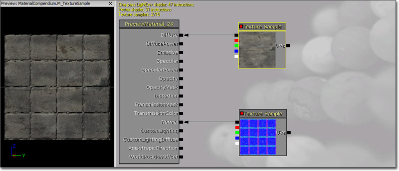
TextureSample
The TextureSample expression outputs the color value(s) from a texture. This texture can be a regular Texture2D (including normal maps), a cubemap, or a movie texture. Properties- Texture - Specifies the texture sampled by the expression. To set the texture, first select a texture in the Content Browser. Then, select the Texture property in the expression's property window and click the 'Use Current Selection' button.
- UVs - Takes in UV texture coordinates to use for the texture. If no values are input to the UVs, the texture coordinates of the mesh the material is applied to are used. If the TextureSample represents a cubemap texture, the UVs coordinate must be a three-channel value rather than just a two-channel value.
- RGB - Outputs the three-channel RGB vector value of the color.
- R - Outputs the red channel of the color.
- G - outputs the green channel of the color.
- B - Outputs the blue channel of the color.
- A - Outputs the alpha channel of the color. If a texture does not contain an alpha channel, connecting the 'alpha' channel to something, while not technically illegal, will always result in zero (black).
TextureSampleParameter2D
The TextureSampleParameter2D expression is identical to the TextureSample except that it is a parameter that can be modified in instances of the material and through code. Properties- Parameter Name - Specifies the name used to identify the parameter in instance of the material and through code.
- Texture - Specifies the texture sampled by the expression.
- UVs - Takes in UV texture coordinates to use for the texture. If no values are input to the UVs, the texture coordinates of the mesh the material is applied to are used.
- RGB - Outputs the three-channel RGB vector value of the color.
- R - Outputs the red channel of the color.
- G - outputs the green channel of the color.
- B - Outputs the blue channel of the color.
- A - Outputs the alpha channel of the color. If a texture does not contain an alpha channel, connecting the 'alpha' channel to something, while not technically illegal, will always result in zero (black).
TextureSampleParameterCube
The TextureSampleParameterCube expression is identical to the TextureSample except that it only accepts cubemaps and it is a parameter that can be modified in instances of the material and through code. Properties- Parameter Name - Specifies the name used to identify the parameter in instance of the material and through code.
- Texture - Specifies the cubemap sampled by the expression.
- UVs - Takes in UV texture coordinates to use for the texture. If no values are input to the UVs, the texture coordinates of the mesh the material is applied to are used. This must be a three-channel vector value.
- RGB - Outputs the three-channel RGB vector value of the color.
- R - Outputs the red channel of the color.
- G - outputs the green channel of the color.
- B - Outputs the blue channel of the color.
- A - Outputs the alpha channel of the color. If a texture does not contain an alpha channel, connecting the 'alpha' channel to something, while not technically illegal, will always result in zero (black).
TextureObject
The TextureObject expression is used to provide a default texture for a texture function input within a function. This node does not actually sample the texture, so it must be used in conjunction with a TextureSample node.TextureObjectParameter
The TextureObjectParameter expression defines a texture parameter and outputs the texture object, used in materials that call a function with texture inputs. This node does not actually sample the texture, so it must be used in conjunction with a TextureSample node. This node is used with MaterialFunctions.TextureSampleParameterMeshSubUV
The TextureSampleParameterMeshSubUV expression is identical to the MeshSubUV except that it is a parameter that can be modified in instances of the material and through code. Properties- Parameter Name - Specifies the name used to identify the parameter in instance of the material and through code.
- Texture - Specifies the texture sampled by the expression.
- UVs - The UV input is ignored and does nothing.
- RGB - Outputs the three-channel RGB vector value of the color.
- R - Outputs the red channel of the color.
- G - outputs the green channel of the color.
- B - Outputs the blue channel of the color.
- A - Outputs the alpha channel of the color. If a texture does not contain an alpha channel, connecting the 'alpha' channel to something, while not technically illegal, will always result in zero (black).
TextureSampleParameterMeshSubUVBlend
The TextureSampleParameterMeshSubUVBlend expression is identical to the TextureSampleParameterMeshSubUV except that it provides the ability to blend between the subimages when using the linear blend or random blend modes in Cascade. Properties- Parameter Name - Specifies the name used to identify the parameter in instance of the material and through code.
- Texture - Specifies the texture sampled by the expression.
- UVs - The UV input is ignored and does nothing.
- RGB - Outputs the three-channel RGB vector value of the color.
- R - Outputs the red channel of the color.
- G - outputs the green channel of the color.
- B - Outputs the blue channel of the color.
- A - Outputs the alpha channel of the color. If a texture does not contain an alpha channel, connecting the 'alpha' channel to something, while not technically illegal, will always result in zero (black).
TextureSampleParameterMovie
The TextureSampleParameterMovie expression is identical to the TextureSample except that it only accepts movie textures (Bink movies) and it is a parameter that can be modified in instances of the material and through code. Properties- Parameter Name - Specifies the name used to identify the parameter in instance of the material and through code.
- Texture - Specifies the movie texture sampled by the expression.
- UVs - Takes in UV texture coordinates to use for the texture. If no values are input to the UVs, the texture coordinates of the mesh the material is applied to are used.
- RGB - Outputs the three-channel RGB vector value of the color.
- R - Outputs the red channel of the color.
- G - outputs the green channel of the color.
- B - Outputs the blue channel of the color.
- A - Outputs the alpha channel of the color. If a texture does not contain an alpha channel, connecting the 'alpha' channel to something, while not technically illegal, will always result in zero (black).
TextureSampleParameterNormal
The TextureSampleParameterNormal expression is identical to the TextureSample but is specifically suited for use with normal map textures and it is a parameter that can be modified in instances of the material and through code. See the NormalMapFormats document for an explanation of why this node is preferable to a TextureSampleParameter2D when specifying a parameter that is used for a normal map. Properties- Parameter Name - Specifies the name used to identify the parameter in instance of the material and through code.
- Texture - Specifies the normal map sampled by the expression.
- UVs - Takes in UV texture coordinates to use for the texture. If no values are input to the UVs, the texture coordinates of the mesh the material is applied to are used.
- RGB - Outputs the three-channel RGB vector value of the color.
- R - Outputs the red channel of the color.
- G - outputs the green channel of the color.
- B - Outputs the blue channel of the color.
- A - Outputs the alpha channel of the color. If a texture does not contain an alpha channel, connecting the 'alpha' channel to something, while not technically illegal, will always result in zero (black).
TextureSampleParameterSubUV
The TextureSampleParameterSubUV expression is identical to the ParticleSubUV except that it is a parameter that can be modified in instances of the material and through code. Properties- Parameter Name - Specifies the name used to identify the parameter in instance of the material and through code.
- Texture - Specifies the texture sampled by the expression.
- UVs - The UV input is ignored and does nothing.
- RGB - Outputs the three-channel RGB vector value of the color.
- R - Outputs the red channel of the color.
- G - outputs the green channel of the color.
- B - Outputs the blue channel of the color.
- A - Outputs the alpha channel of the color. If a texture does not contain an alpha channel, connecting the 'alpha' channel to something, while not technically illegal, will always result in zero (black).
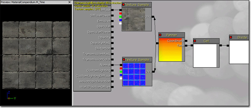
Time
The Time node is used to add the passage of time to a material, such as a Panner, Cosine, or other time-dependent operation. Properties- Ignore Pause - If true, time will continue to march on even if the game is paused.

Transform
The Transform expression converts a three-channel vector value from one reference coordinate system to another. By default, all shader calculations in a material are done in tangent space. The vector constants, camera vector, light vector, etc are all transformed to tangent space before being used in a material. The Transform expression allows these vectors to be transformed from tangent space to world-space, local-space, or view-space coordinate systems. In addition, it allows world-space and local-space vectors to be transformed to any of the other reference coordinate systems. Properties- Transform Source Type - Specifies the current coordinate system to transform the vector from. This can be one of: World, Local, or Tangent.
- Transform Type - Specifies the target coordinate system to transform the vector to. This can be one of: World, View, Local, or Tangent.
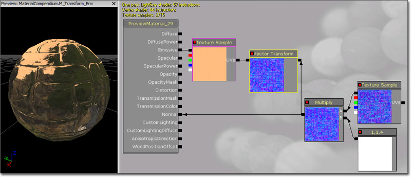 Transforming normals to view space can be used for creating edge-on effects. This can be achieved by using mesh normals to generate texture coordinates (commonly referred to as "Sphere Mapping"). With this method, normals facing directly at the camera will map to the center of the texture coordinates, and normals facing perpendicular to the camera will map at the edge of the texture coordinates. Here is an example of Sphere Mapping:
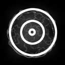
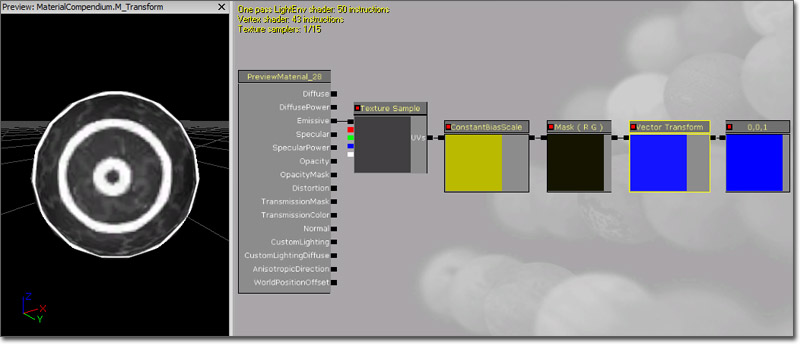 A constant3vector with a value of (0,0,1) is fed into the Transform with TRANSFORM_View set, which is then passed through a ComponentMask (Passing through only R and G). Since the Transform will output a range of values from -1 to 1, we must bias the values to put them into the 0-1 range. This is done by multiplying by 0.5, and then adding 0.5. Then simply plug that into the Coordinates of a texture. Any texture will work; I made one with three rings so that the effect is obvious.
 To use this effect with a normal map, simply substitute the Constant3Vector with a normal map texture.
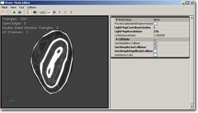
Here is an example of this spheremap material applied to a blob-like rock mesh:
To use this effect with a normal map, simply substitute the Constant3Vector with a normal map texture.
Here is an example of this spheremap material applied to a blob-like rock mesh:
TransformPosition
This node is deprecated due to major precision problems when used to derive world pos away from the origin! Use the WorldPosition node instead. The TransformPosition expression can transform any position from screen space to the destination space specified by the expression's TransformType variable. Currently only transforming into world space is supported. This expression can be used to get world space coordinates in the material. To visualize world position, you can plug it straight into emissive: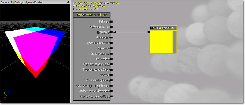 You can also use world position as planar texture coordinates:
TwoSidedSign
The TwoSidedSign expression is useful for flipping the normal on backfaces of two sided custom lighting materials to match the functionality of Phong. +1 for frontfaces, -1 for backfaces of a twosided material.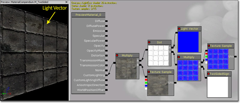
WorldPosition
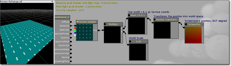
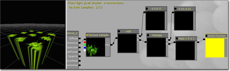
The WorldPosition expression outputs the position of the current pixel in world space. To visualize, simply plug the output into Emissive: Common uses are to find the radial distance from the camera to a pixel (as opposed to the orthogonal distance from PixelDepth). WorldPosition is also useful to use as a texture coordinate and have unrelated meshes using the texture coord match up when they are near each other. Here is a basic example of using WorldPosition.xy to planar map a texture:
WorldNormal
The WorldNormal expression outputs the world space vertex normal. It can only be used in material inputs that are executed in the vertex shader, like WorldPositionOffset. This is useful for making a mesh grow or shrink. Note that offsetting position along the normal will cause the geometry to split apart along UV seams. (Hover for animated preview)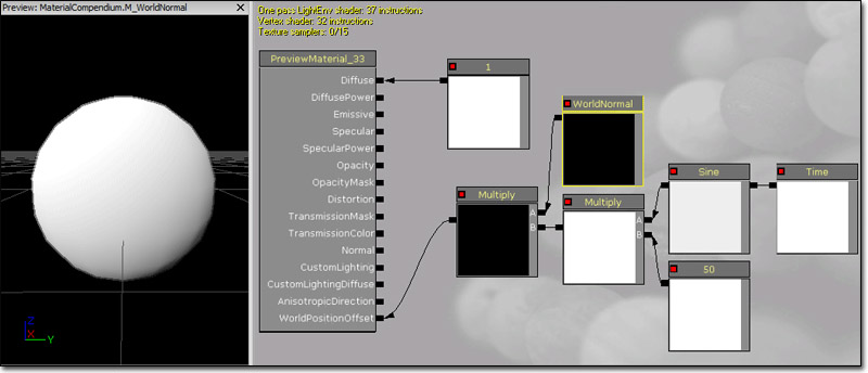
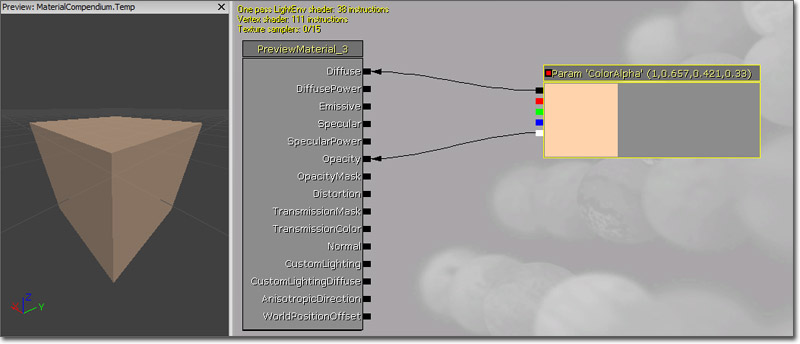
VectorParameter
The VectorParameter expression is identical to the Constant4Vector, except that it is a parameter and can be modified in instances of the material and through code. One nicety of the VectorParameter is that its value can be set using the Color picker. Properties- Default Value
- R - Specifies the float value of the red, or first, channel of the vector the expression outputs.
- G - Specifies the float value of the green, or second, channel of the vector the expression outputs.
- B - Specifies the float value of the blue, or third, channel of the vector the expression outputs.
- A - Specifies the float value of the alpha, or fourth, channel of the vector the expression outputs.
- Parameter Name - Specifies the name used to identify the parameter in instance of the material and through code.
VertexColor
The VertexColor expression is the access point for the material to the outputs of color modules affecting sprite particles emitters. Outputs- RGB - Outputs the three-channel RGB vector value of the color.
- R - Outputs the red channel of the color.
- G - outputs the green channel of the color.
- B - Outputs the blue channel of the color.
- A - Outputs the alpha channel of the color.